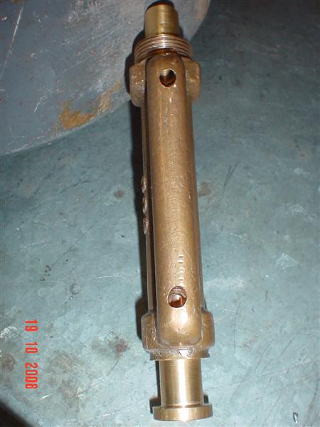
LEFT: The fuel pump
when factory made had a core made for the bypass tube as can be seen
here 1, in machining a solid block
casting I had to drill this section out, as can be seen on the photos
as we go.
Area 1 is the cast bypass tube, 2
shows the two check valves, 3 shows
the plunger spring, this is tapered. 4
is the intake tube filter, 5 is the
pump piston, 6 is a 1/8 NPT square
head plug for draining. 7 is the fuel
line to mixer. 8 is a breather hole,
around 1/32" to prevent air locks ( I guess), 9
is a hole to allow excess fuel that bypasses piston to flow back to
tank.
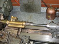
Above: The pump bore
was first drilled with a pilot drill, then a 39/64" drill, then
reamed to 5/8" with a parallel machine reamer. I got away with
out using a steady by taking it slowly. The 3/4" mounting thread
was cut first, then I made a jig to take the pump by screwing it into
it and then held that in the lathe. Griping the jig tightly rather than
griping and marking the pump body in the chuck.
|