| FEATURED ENGINES | |||||
|
|
||||||||||||||||||
|
| The Cams |
|||||
Click on images to enlarge
them |
|||||
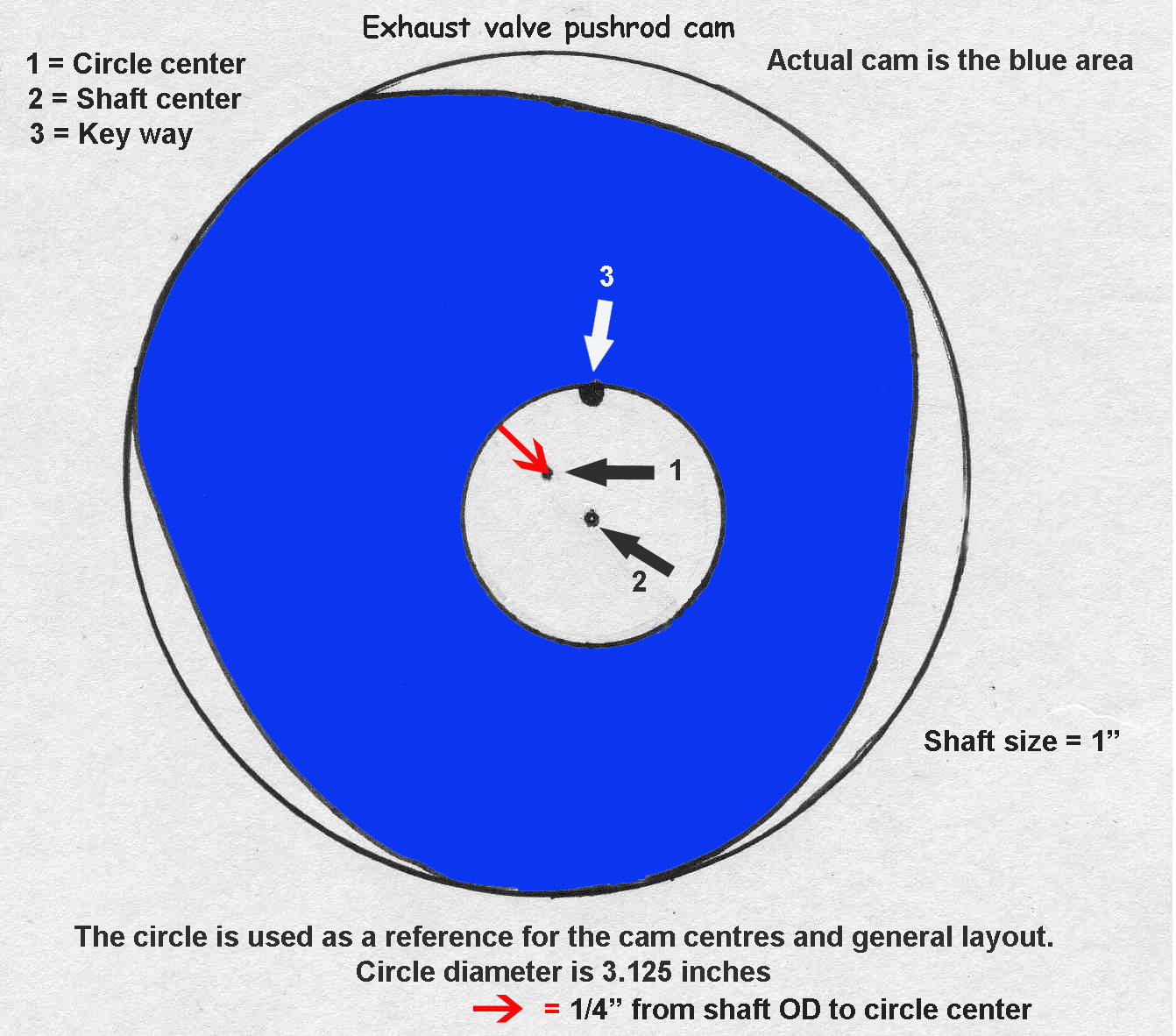 |
This is the exact layout of the two cams
that drive the exhaust valve and fuel pump. The circle was used as a reference
and the cam was traced from the original cam. R&V part No. 33B |
 |
|||
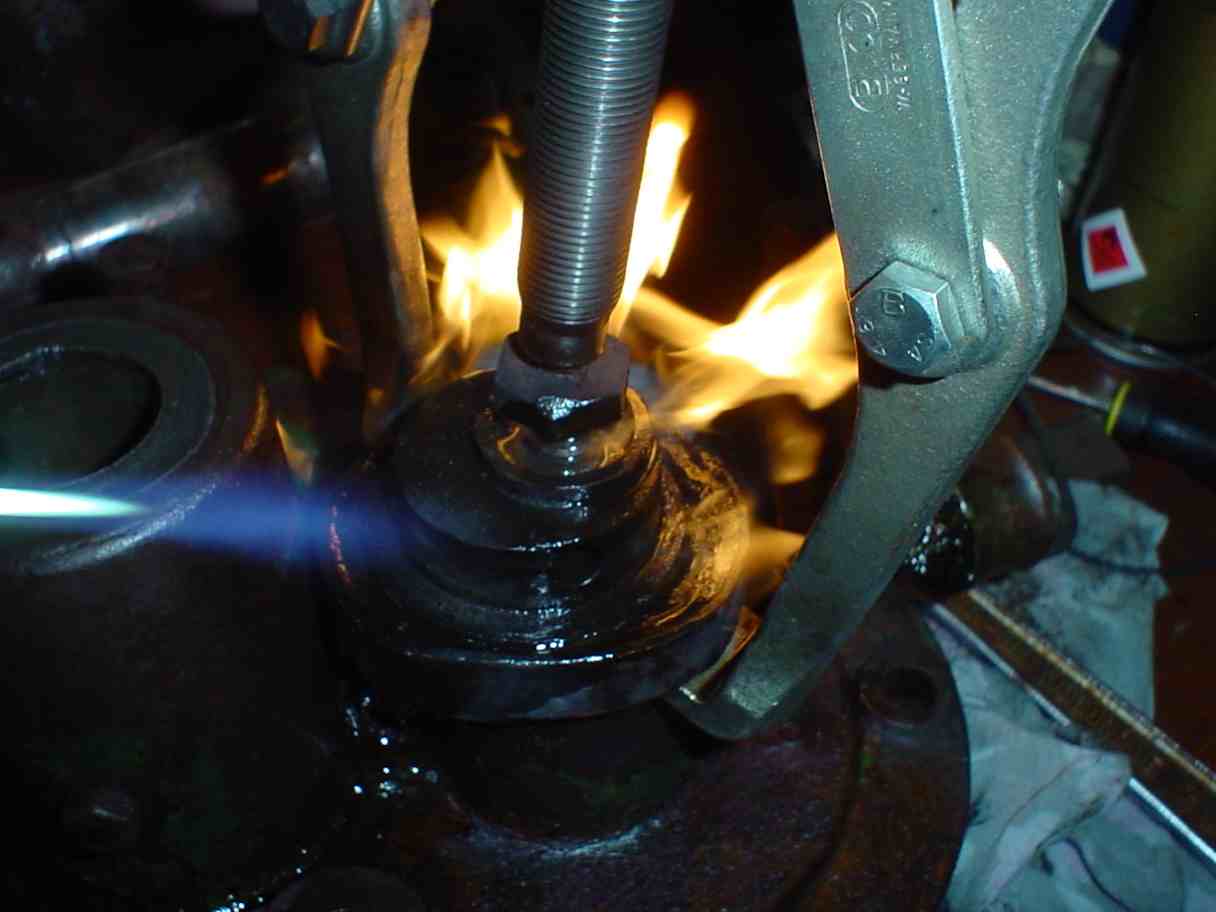 |
Left shot shows heating the
cam while using a bearing puller, it was extremely tight and we all know
you take care with cast iron. The right shot shows cam half way off. |
 |
|||
 |
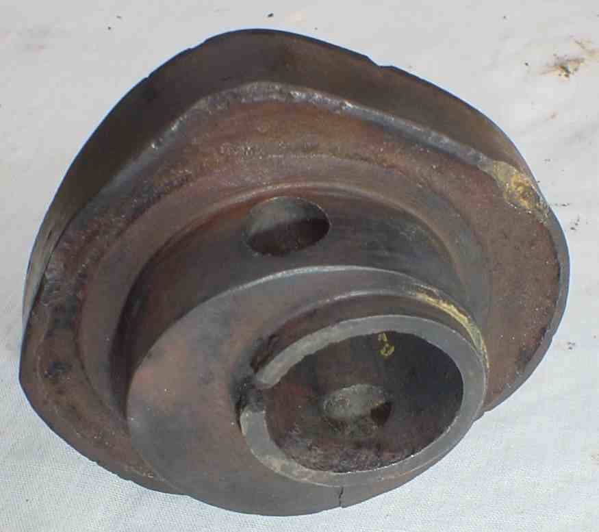
Left: The
cam removed, the hole on the end of the shaft has been placed there when
it was modified to points and coil, it held a third cam in place to run
the points. Normally the main cam is just keyed on. R&V Part No. 14B |
 |
|||
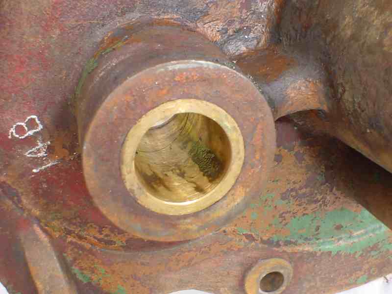 |
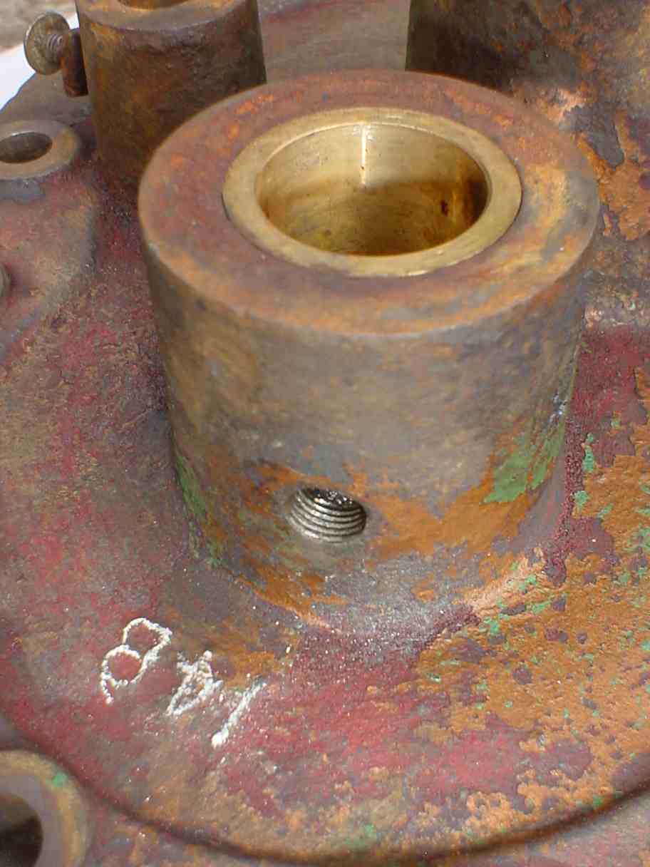
Bearing housing
is R&V Part No. 14B |
 |
|||
|
Showing Cam profile R&V Part No. 33B |
 |
|||
|
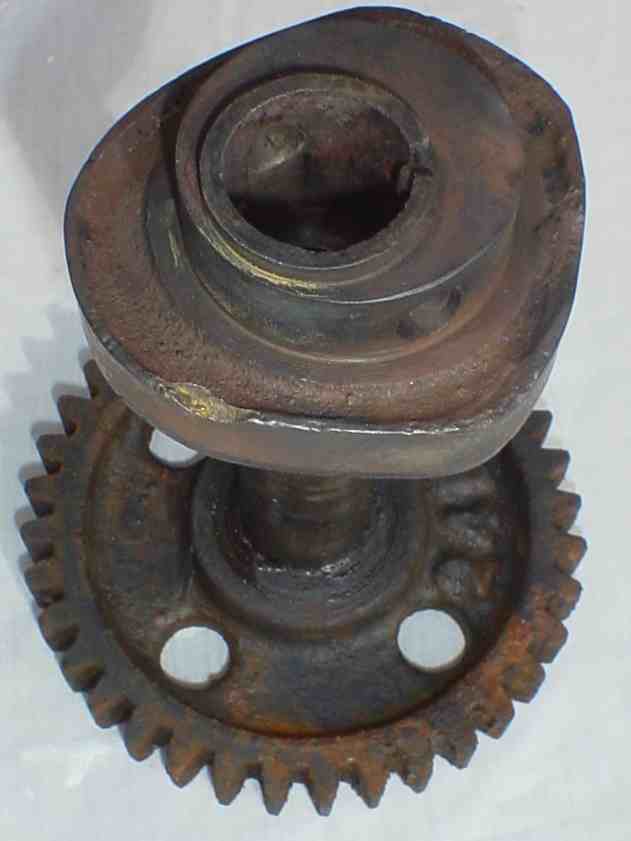
The complete cam, shaft and cam gear |
||||
 |
|
Left: Cam Gear - 36 teeth
Right: Main crank bearing from removable bearing housing. These are a solid bearing with no adjustment, as you can see to oil comes in from the hole on top, along the groove and into a radial ring on both ends. |
 |
||